This is my final project for IMGD300X. I got to choose the concept, design the project, and had to assemble it myself.  You can see my concept explained in my blog post here: http://www.joshuarosenstock.com/teaching/IMGD3200_B13/final-project-idea-madalyn-coryea/

Here’s a basic overview of what I did.  I always enjoyed building card towers as a kid, and I thought it was cool how you could be creative and build the card tower in any way you wanted. The structure would always look different, even though you were building with cards.  So I decided to go with this concept for my final project.  I created a board using graphite (pencil), alligator clips, posterboard & cardboard, and the Makey Makey that would allow the user to build “card towers”.

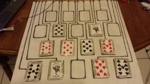
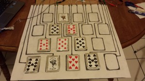
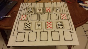
My concept was that the user could use real playing cards to form different patterns on this board I created.  Then the patterns would “come to life” on the screen through PureData.  I wrapped the backs of 10 cards in aluminum foil.  With these 10 cards, one could create one of four patterns on the board: a pyramid, a fortress, a castle, or a tornado. (Below are pictures of each of the 4 formations on the board)

pyramidfortresscastletornado

See the video of this all working below: (You can see the cards appearing in “blue” on the screen as they are being put down. This means the key was registered and the input was stored.)

http://www.youtube.com/watch?v=iFweRXP06PA&feature=youtu.be


I have my boyfriend helping me out in the video. By him holding the ground, and me holding his hand, we make a circuit for the system to work.

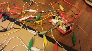
Here is a picture of my Makey Makey set-up with all 18 alligator clips connect to the 18 different ports. The black alligator clip is the ground. The clips are connected straight from the Makey Makey to the posterboard that has the card-outlines drawn in graphite.

makey makey


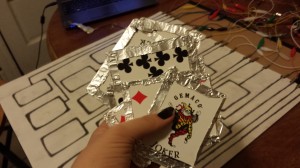
Here are the 10 cards I used. Each has the back of it wrapped in aluminum foil so that they are conductive as part of the circuit.

aluminum cards

This works because each of the 18 spaces on the board is hooked up to a different “key on the keyboard” through the Makey Makey. One of the obstacles I faced with this project was getting all 18 inputs to work with the Makey Makey.  This is because not every input on the Makey Makey is associated with a key on the keyboard. Out of all 18, 11 inputs deal with keyboard keys and 7 inputs deal with mouse data.  So instead of pressing “a” or another key, when you hook something up to one of the other 7 inputs you’ll get a “mouse click” or something else to do with the mouse.  This data was tricky to read, so I thought it best just to reprogram the Makey Makey to read keys for these inputs instead.  I did this by changing some of the Makey Makey’s code in the Arduino Environment (the Arduino IDE) through the course of following some very helpful tutorials.

If you try reprogramming the Makey Makey for yourself, here is the link to the tutorial I used: https://www.sparkfun.com/tutorials/388

I had some trouble getting my computer & Arduino IDE to recognize the Makey Makey correctly, but after that was done, it was really quite easy. I will break down the steps for you:
1.) Plug the Makey Makey into your computer

2.) Download the Ardiuno IDE (if you haven’t already).

3.) Figure out where the files for the Arduino IDE are stored on your computer

4.) Then, you are going to download the Makey Makey addon and put it where they tell you

5.) Now this was the hard part for me. Follow the bottom half of this tutorial for getting your computer to identify Makey Makey correctly: https://www.sparkfun.com/tutorials/378. You’re going to want to download the real driver that they give you a link to, otherwise your computer (Windows) will just read the Makey Makey as “USB Input” or something like that. Give your computer the folder where the driver is like they show you in the tutorial, click “yes” to the scary message, and presto, you’ve got your computer identifying the Makey Makey. (My computer freaked out here, and I had to redo some of this process but hopefully it works better for you).

6.) Now open the Arduino IDE. Select the port (COM4 or something like that). Now select the device. If yours says Makey Makey, great! Select that. No matter what I did, I couldn’t get the Makey Makey device to appear in this list, but I just selected “Arduino Leonardo” here and it worked fine.

7.) Back to the first tutorial. They give you the code in a zip file that tells the Makey Makey which key is which. Download this.

8.) Once you’ve downloaded & unzipped the code, open it in the Arduino IDE (by double-clicking it or whatever. however you normally open things)

9.) Make sure you can see/access the settings.h file. This is what you change.  (They have this file commented nicely. It’s pretty clear what keys go with which points. So just change whatever you want).

10.) When you’re done changing inputs, Verify & Upload the file to your board, just like you would any other Arduino program. (The Makey Makey should blink a bit, but when the load bar completes, try it out! The keys should be different now; whatever you changed them to.)

I hope you enjoyed my project. It was fun to make, even if it took awhile.  I did have to run out and buy more alligator clips than the Makey Makey provided (19 in total! –one for each input + the ground). My idea for expanding this is to have MANY more combinations of exactly 10 cards on the 18-card sized grid to make different patterns. I would also like to have the actual cards appear on the computer somehow as you place them. There is so much that could be done with this concept. However, if you ever play with it, it is really fun, and I enjoyed building cards with it very much.
For this project I put most of my effort on making the Pd patch to work so my video explains the patch in detail. I tried to explain most of the aspects clearly since I think I wasn’t able to do that in today’s presentation in class.

I put a lot more effort in this video as it is my final video for IMGD 300X (it is available in 1080P). Ask me any other questions with Pure Data if you have any. It was nice working with everyone, and the professor and SA. Thank you very much and have a nice holiday!

Project by:

Sam Stadtlander

Adrienne Weishaar


Using a Makey Makey, Conductive Thread and PureData, we were able to create a controller for a bunch of animations.

The dragon was crocheted using regular acrylic yarn. To trigger the MakeyMakey we used conductive thread hidden throughout the dragon. The animations were made on Photoshop and the sounds were imported from different free audio sites. Enjoy the video!

For my final project in IMGD300X, I came up with the idea of making a metaphor with “card towers”.

It is a lot of fun to build card towers, so I came up with a board that lets you build card towers that turn into actual things through PureData.  I will be using real playing card to build a “card tower” on the screen through PureData.  With the board that has a set number of card spaces, you will have 10 cards to arrange in any order you choose on the board.  There are set patterns that will create a diagram and then an animation on screen.  Create one of these special patterns and you will get an animation of the diagram/shape you created. If you create a pattern that is not one of these, there is a default animation you will get.

The board is set up with alternating rows of 4 or 5 card spaces. There are four rows total. Each space is hooked up to a different key on the Makey Makey. The cards in the alternating rows are slight displaced from one another so that there is a shift in the spacing between cards of different rows. This allows for a large amount of design patterns.

An example of how the board is set up is below:

[] [] [] [] []

[] [] [] []

[] [] [] [] []

[] [] [] []


So I am going to use the MakeyMakey to hook up the different playing cards to the computer. Each card will have aluminum foil on it’s back so it can complete a circuit with the board where the cards are placed.  Each card space will be traced out in graphite pencil and then the graphite trail for each space will be hooked to the MakeyMakey with an alligator clip.

I also really want it to be able to tell which cards are put down, so that once a card is placed, it is put in the correct place on the screen (which will display the real-life board with all the available position). This may or may not be possible at all.

Mainly, for research I need to make sure this is possible in PureData. I already know that I can put pieces of aluminum foil on the cards to make them conductive for the MakeyMakey. And I know that I can display an image on the screen when a key is pressed on the keyboard. What I need to find out, is if I can determine the order in which the cards will be displayed on the diagram I am going to form. I think with some logic it should all be possible. I just really want to make sure that I can detect the when all the correct keys are pressed to play the correct animation. Switching out the screens may be difficult. I also don’t know if I can display the correct cards on screen for each space. If this is not possible, I could just display a blank card on the screen. Or as a last resort, I could display nothing on the screen except for the animations.

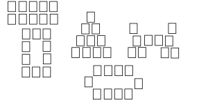
This image shows a (rough) mock of some of the diagrams (with respective animations or pictures) that I am going to form.

card_layouts_imgd


They are: a pyramid, a castle, a fortress, and a tornado (not shown). The default will be a collapsed pile of cards. I am going to try to make as many cool diagrams as I can that are metaphors, and integrate them into the system.

For the final project, I decided to make a rock paper and scissors game where you use literally a rock, paper, and scissors.

Here is the sketch I drew in MS Paint that explains what I want to do:

rps

So I am using the rock, paper, and scissor objects as metaphors to the rock, paper, and scissors used in the actual game (or should I say it is more like a reverse-metaphor?) I will make the program part itself all within Pure Data, I think that would be easy enough since I was able to make a game-ish thing when doing the interactive drawing project. Since we only have a week or so I decided to go with a simple game like this. Basically, I will use metro objects for timing and toggle objects for checking which object is selected and binary operator objects for condition checking. I may need some research on details of pure data objects such as the text2d object and how to use the float object. To actually make use of the rock, paper, and scissor objects, I think using the Makey Makey would be a lot simple and easier than the Arduino since I am not doing anything complicated with inputs/outputs. During the weekend I will try to make most of the Pd patch and next week I will borrow the Makey Makey and try it out.


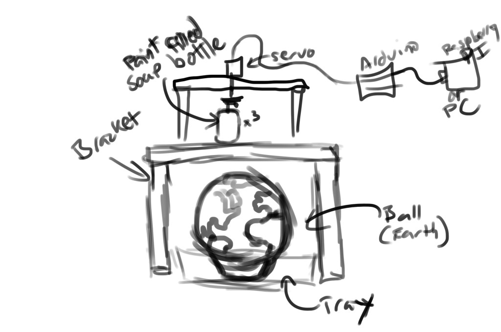
For our assignment, we plan on playing off the Sherwin-Williams metaphor “Cover the Earth”.

Cover_the_earth


After seeing this logo on a sign in Shrewsberry, it looked like it could pose as the perfect concept for an interactive art project.

We plan on making a wooden frame that will hold three different dispensers of paint (Red, Blue, and Yellow). A globe will be placed inside the frame. When the user presses a corresponding button on the computer on the computer (or physical button), the Arduino will activate a servo which will push down on a dispenser filled with paint.

Concept

We’ll need to figure out how to mount the servo/dispensers together to make them work properly, as well as figure out how to actually hook up a servo to the Arduino. So far, we have the paint, wood to make the frame, and a make-shift globe.

This could turn out to be a really fun interactive piece; we’re pretty excited to build it.

– Dan & Derek

My steup for the arduino board was very straighforward. All sensors hooked up to the bread board at once with them all using the same ground. I used the soft potentiometer, the thermal sensor, and the flex sensor. Here as you can see when i vary the value of the soft potentiometer the circle becomes larger and smaller. When the flex sensor is applicated the circle changes from yellow to red, with a mix of orange depending on where you are in the middle. Lastly the thermal sensor simply moves the circle right when heat is applied with my hand. Enjoy!

Let me first apologize for the poor quality of the video. My demo used 3 sensors, the soft pententiometer, the flex and temperature sensors. In the first video below, i use a flex sensor to control 3 different shapes. It controls attributes like translation, rotation, size and color depending on how much it is flexed. In the second video the soft pententiometer controls how many animations are being played… 1 ,2 or 3. Finally the temp sensor controls the opening of a gem window when it reaches a certain temperature.