Final Project – Digital Etch-a-Sketch

This is the final demo of my digital Etch-a-Sketch. The screen recording was at a lower frame rate than the actual processing script making the drawing look choppy.

Overall I am pretty happy with the results. I think there could be some work done on the velocity portion of the demo, either by applying a filter to the velocity to smooth it out or by using a timer to regularly sample the difference in distance.

Enjoy!

Final Project II: The Switcheroo

In my first post about my final project I provided photos of a stepper motor, stepper driver, and FPGA development kit.

I will use none of those for my final project. Why? It turns out that getting high resolution rotary encoders for free is very difficult. Instead I shall be using the following parts:

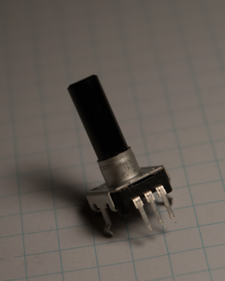
Simple Knob Rotary Encoder
This is a simple rotary encoder which has 24 counts per revolution and reports angular change via quadrature encoding. Quadrature encoding is a very cool method of transmitting the angular change as you can both artificially increase the resolution 4x but also tell the direction of rotation. See this article for details. Specifically read the “Further Description, Including Encoder Waveform” section.

Breadboard and Jumpers
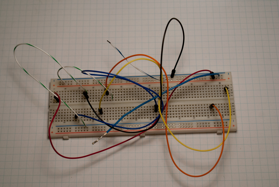
Breadboard and jumpers
Just a standard breadboard with jumpers.

Arduino Leonardo
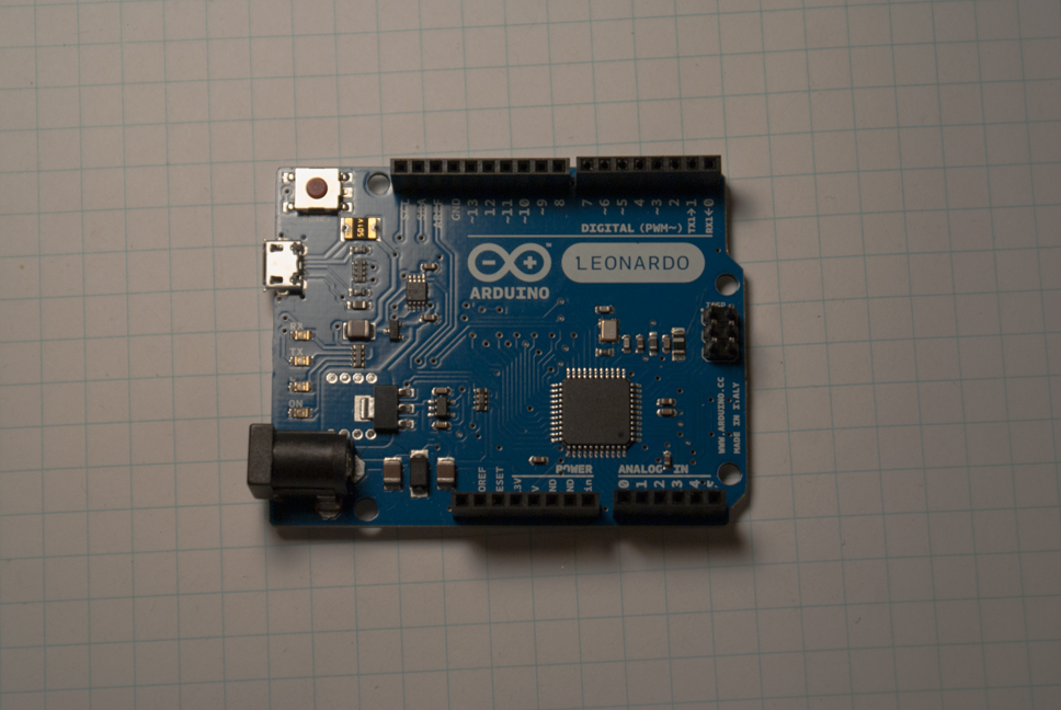
Arduino Leonardo
The Arduino Leonardo is an updated version of the Arduino Uno. It is less expensive to manufacture and has an updated ATMega microprocessor. I choose this part mainly because it has 4 available external interrupts while the Uno only has 2.

Project Goals
My goal with this project is to produce a virtual etch-a-sketch. I will further extend the etch-a-sketch concept by including velocity data into the drawn lines in some form or another. I could modulate the stroke width, the color, or both.

Project II: Meme Mashup

When I started this project I wanted something to do with the Leroy Jankins meme. As you may know it is really an auditory meme. From there I thought I could do something where you would press a button and you would get LEEEEEEROY JAAANNNKINS and a video would go crazy. After getting the audio clips and a few movies together I decided that it didn’t really go together very well. I then decided that I would like to incorporate more sound so I started cutting samples out of other songs. I ended up with clips from Harder, Better, Stronger, Faster by Daft Punk, Bananaphone by Raffi, and the original Leroy Jankins clips. As I started putting them together I was trying to think of a cool visualization that I could add. Eventually I ended up looking at a bunch of Youtube videos with the lyrics super imposed. This gave me the idea that I could essentially make the lyric corresponding to the sound clip pop onto screen and then fade out over time. Here is the result:

To get a good idea of what is going on I recommend viewing the video in full HD in full screen. To do this you just need to click the “Youtube” button in the Youtube player. This will take you to Youtube where you can view the project in its full glory.

Inspiration

I suppose inspiration comes from many places. I would like to think of myself as someone better versed in the types of art presented in this class than the general public, but I would point out the general public has a very broad taste.

When discussing VJs and visual/audio art the first piece that popped into my head was “The 600 Years”:

The 600 Years from the macula on Vimeo.

Talk about impressive. I am impressed at the time it took to make such a spectacular show. Further the detail was exquisite. The tower truly looked as though it was alive.

I think this kind of art carries heavy weight in that it both combines the new and old and possibly restores interest in older cultural icons. Due to this piece I could easily see some young blood so to speak looking into ways to improve the clock tower and entering the historical society surrounding such historical monuments.

I myself am fascinated by the blending and combination of different projectors to produce such impressive displays. The amount of math and geometry surrounding such a display truly boggles the mind. The Latin metaphor nani gigantum humeris insidentes succinctly expresses my view. (The Latin stands for Dwarfs standing on the shoulders of giants)

Nature vs Machine

Making something seem natural can be a difficult thing. What does it mean for something to be natural. I think that naturally occurring things can also have seemingly unnatural properties. Take crystals for instance. If one had never seen a crystal before in their life and had made it a while in a mechanized society I suspect they would find it hard to believe that the crystal was natural. Another instance is of things on a micro scale. Again the objects would seem unreal and man made.

The first thought that I had in making something natural was to make something like an ant farm with connecting and wandering tunnels. The following is a result of my pursuit of an ant farm.

As you can see it looks nothing like an ant farm. Essentially what is going on in this is a point is initialized then has a probability of duplicating. The point and potentially its duplicate then move a random distance in a random direction. To ensure that the animation always runs smoothly, first, points off the screen are deleted, and second, if there are more than N points then we delete the oldest points till there are only N. N is a configurable number here.

The next script I wrote tried again to realign with the ant farm idea. I definatly was closer but I think I may have gotten it upside down.

We now have some sort of growth maybe like a tree. When you click (hopefully) the animation will start over with a new color. I think you can get some pretty cool colors all things said and done with this.

I also wanted to have something chase the mouse around the screen. I though it might be interesting to have waves following the mouse that varied orthogonal to the vector pointing to the mouse location from the current draw location. My first attempt did not work out as well as I hoped.

As you can see the lines move radially to the mouses location rather than having the variation orthogonal to the vector mouse location. It still is a pretty interesting effect and I rather liked the way you could make the lines compress and grow depending on how you used the mouse.

Finally I actually got the lines to move in the way I originally intended. Here is the result:

This fulfilled my goal though I found it annoying the way that each line was not moving quite the way I wanted it too. I envisioned it such that each varying stream would move at a constant “speed.” However if the mouse is close to the location the lines are being drawn and move around the animation can move very quickly.

Basic Components for Final Project

I have started gathering components for my final project. Essentially I think that I want to have mechanical feedback into my system. I think that I am going to try and use the following components:

NEMA 17/23 Stepper Motors
NEMA 17 Motor
I have a set of NEMA 17 and 23 motors. Essentially a NEMA motor is a motor which conforms to the NEMA standard. The 17 and 23 refer to the size of motor 1.7″ x 1.7″ and 2.3″ x 2.3″ respectively.

US Digital MD2S Stepper Drivers
US Digital Stepper Driver
The US Digital Stepper Drivers are microstepping drivers. Stepper motors have a series of fixed positions which they can “normally” be in. My motors have these positions every 1.8°, however, it is possible to resolve smaller angles using microstepping. To read more on microstepping see this article:

Terasic DE0-Nano
Terasic DE0-Nano
The DE0-Nano is probably the best FPGA development board I have seen to date. What is an FPGA you might ask? FPGA stands for Field Programmable Gate Array. Gates are the fundamental blocks of digital circuits these days. Your desktop computer has many of these gates within its CPU which form the hardware to perform a variety of operations such as adding, subtracting, multiplication, and division. The difference between your CPU and an FPGA for this example is that the gates in a CPU have a fixed purpose. That is, some of the gates in your CPU are used to make an adder and others a subtractor and these gates will always an adder or subtractor. In an FPGA however you could reconfigure the gates such that they form a multiplier or anything else you could design.

So in my design I have arranged the gates such that they form a very small CPU much like that found in an Arduino (technically an Atmel AVR core) or similar microprocessor. I can interface this CPU to custom peripherals such as a stepper motor driver.

Where do I want to go with this?
I do not know. My first though is some sort of Cartesian drawing machine but that may prove to be to complex for the time allotted and I may have to focus on a polar drawing machine. Maybe I will do something that does not incorporate drawing at all. If I get some encoders maybe I will make a digital etch-a-sketch.

Who knows.

First Stab at Processing

The following images/animations are the result of my first processing sketch.

This first sketch is a static drawing. I essentially wanted to replicate patterns that I would draw in Photoshop by performing and repeating a transformation. I learned about pushing and popping transformation matrices to perform these transformations.

I then extended this sketch to be dynamic. I initially started by making the background move and shift as the mouse moved and shifted. I then made the color and shading of the shapes change as the mouse moved around the sketch. With both the background moving and the colors/shading changing I found the sketch to be nauseating; there was just too much going on. I fixed the background and added functions to allow the scene to be either automatically changing or change with mouse movement. The change mode can be toggled by clicking on the sketch.