Progress Report 1

Progress Report 1

I started thinking about materials and implementation. The main parts of the design will be: 3D glasses, paper (or similar) to project through, a transparent water tray, light sources, and some kind of frame or scaffolding to hold everything in place.

I ordered 50 3D glasses for only 40¢ from American paper optics.

For the transparent water tray, I immediately thought of a Pyrex baking dish, but these are small. Then I thought of ripple tanks for physics experiments, but all of the ones on amazon and ebay come with vibrating wave makers which make them expensive. Then I found some youtube videos of how to make your own aquarium from Plexiglas and special solvent cement. This seems cheapest and not too hard. Maybe I can figure out how to laser cut the Plexiglas – I see robotics majors do it all the time.

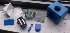
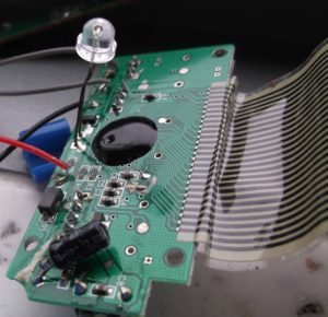
I first pictured the light sources as spotlights. However, these must be far from the subject to create hard shadows. I needed a point source such as a very bright LED. I needed to find an unusually bright LED to experiment with, so I took apart my alarm clock (see below) and used the one inside.

alarm clock1 alarm clock 2

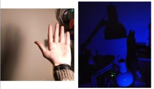
It created very crisp shadows, unlike my desk lamp.

hard shadow

I was worried about finding the exact red and exact cyan that would be compatible with the 3D glasses. I came up with a clever solution: just use white LEDs and filter the color with a second pair of 3D glasses. I then ordered some white 10 lumen LED’s (which is apparently very bright) from a website called superbrightleds.com. Aptly named!

Finally I thought about the frame or scaffolding. I have seen reusable metal prototyping channels, called 80 20, used in several MQP’s and at my summer job. They would be ideal, but unfortunately it would cost about $70 for the amount I want. A cheaper alternative is to make something structural out of cardboard. While it sounds like a weak material, it can be quite sturdy when there is enough of it. Prof. Rosenstock suggested PVC which I think is a great idea.

Project Ideas

I have three ideas.

1) 3D caustics

2) Moving color pattern

3) Spinning reflective curve tracer

I will go through each of these.

  • 3D Caustics

I have fooled around with 3D glasses before. For example, I have combined photos taken an eye width apart into 3D images using Photoshop. Something that has been in the back of my mind for a while is: could a 3D image be created another way, without Photoshop or even computers in general?  According to Instructables, people have already made multiple types of camera attachments for this purpose, so I guess that was not an original idea. The concept of this class, ‘Light art’, and artists who use light to project shadows, gave me a more original idea: to create 3D images without even a camera by using shadows. If two light sources are mounted an eye width apart, one red and one cyan, the shadows projected should theoretically be viewable under 3D glasses. This is because the two light sources are analogous to the two eyes of the viewer, ‘seeing’ the object from two directions. The 3D glasses show each of our eyes what just one of these light sources is ‘seeing’. I made the sketch below to illustrate this.
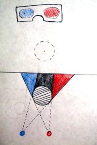
3D shadow low res

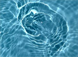
Notice that the image is projected onto paper and seen from the other side by the viewer. The positions of the eyes and light sources are mirrored across the plane of the paper, so the perceived 3D object’s orientation will be mirrored from its actual orientation. Also, the red light source must be on the same side as the red lens. Perhaps this technique could be combined with raw film to preserve the images without a camera? However, it is more of a demonstration than an interactive piece. I was brainstorming about project ideas with Alex Wald and he mentioned that he might use fluids in his project. This gave me the idea of viewing caustics in 3D. If you haven’t heard of caustics, they are refracted patterns such as those seen on the swimming pool floor, pictured below.
Picture1

Caustics would be an interesting subject for two reasons: 1) the user can interact with the water, and 2) the 3D shapes visualized would not a direct representation of the physical fluid shape, but would visualize the data in another way. These shapes would still be 3D, because of the two light sources, but what would they look like? What would their properties be? I would love to play with this!

  • Moving color pattern

My roommate recently got an RGB strip for the room. It came with a remote with many colored buttons. I noticed that when viewed under the changing lights, the colored buttons changed drastically.

remotes

I was aware of this effect before, but this reminded me of it and gave me an idea. Could a printed color pattern be made such that as the incident light color is varied, the pattern appears to animate? The pattern could be printed out, and the incident light could be supplied by RGB LEDs or by light passed through a multicolored rotary filter. In developing this, my first step would be to consider the motion of the darkest area as the light changes. Maybe I could start with something simple like dark spots moving around a circle?

  • Spinning reflective curve tracer

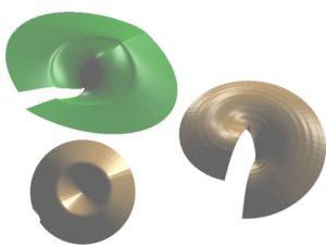
This is an idea that I already started working on this summer (is that cheating?). I was a passenger on a long road trip on the highway and I was looking at the hubcaps of the other cars. I noticed that as they spun in the bright sunlight, they traced out intricate patterns. I started to wonder, what if this process could be reversed? What I mean is, given a desired curve you want the hubcap to trace out, can you design the hubcap that will produce it? One novel application would be to allow a car company to advertise its logo on the hubcap in a very eye catching way. I did a lot of math and thinking about this, but I won’t bore you with the details. I will summarize the basic idea. I first made the simplifying assumptions that the sun is infinitely far away and your eye is at the same height as the hubcap. Then, any point on the hubcap that is bright must be inclined at 45 degrees at that time to reflect at your eye. Using this insight, we can determine the slope at any point on the hubcap. Slope is the same thing as derivative, so the three dimensional shape of the hubcap can be determined by numerical integration. I wrote a program in Matlab that takes in the desired curve, finds the 3D point cloud by numerical integration, and saves it to a file. This file can be imported into Solidworks and tampered with. The next step would be to CNC machine or 3D print it. It would have a rough surface if 3D printed, but I read online that 3D printed parts can be given a mirror smooth polish using acetone vapor. There is some flaw in either the math or the code because the hubcaps don’t reflect exactly as they should in Solidworks. What if it takes a long time to fix? Below are pictures of some output shapes.
hubs

I am leaning towards 3D Caustics.

Project Progress (week 2)

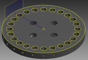
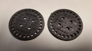
In the past week, I have fabricated and designed a few parts of the project. Above the 24 RGB LED ring will be 24 acrylic rods. Each rod will extend upwards from an LED. The rods will be held in place by 2 discs each with 24 rod holes and 24 pin holes.

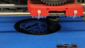
I used Autodesk Inventor to design the discs and then 3D printed them. Below are images of the design on the computer and the discs during and after printing:

Disc_24_HolesDisc_printing Disc_printed Disc_printed Disc_printingIn addition to the discs, I started designing a way to produce interesting lighting effects on the LED ring. I thought of a mathematical software model where each LED is backed with a block that can send information to and receive information from the adjacent LED blocks. Each block will have an internal state that is converted to LED output and all 24 blocks will update periodically. I believe that because this a very general technique rather than a list of preprogrammed explicit patterns, it will produce interesting and unexpected lighting effects.

Project Progress

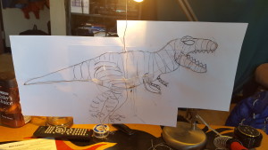
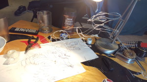
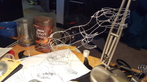
I now have the wire skeleton of T-rex built. I first increased the size of my sketch and started to make the silhouette by taping the wire down every few inches. Then I worked on 2D versions of the arms and legs. I started to build one half the dino on top of the paper and attached an arm and a leg. I then removed it from the paper and worked on the other side. I added supports to the arms and legs to give more shape and support. I finished it up by  adding features to the head like the eyes and teeth. I ordered the el wire, sound reactive inverter, and heat shrink tubing which I need to wait on to progress from here.20160407_00263220160410_15002020160410_16502120160411_12424220160414_180115


Project Progress

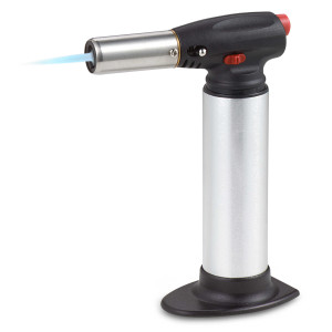
My new candy thermometer just came in yesterday. The LED lights should be coming in tomorrow so I can start to play around with the orientation of the lights and how to hook them up. So far I have been messing around with different ways to incorporate color into the sugar. Originally I thought that I could just heat up a knife under hot water to cut holes in the sugar globes. Unfortunately, that doesn’t make the knife hot enough. Although it takes more cleanup, I got my torch from back home so I’ve been torching knives to get them hot. This has been giving a very clean cut and has been more fun.

torch

Final Project Idea

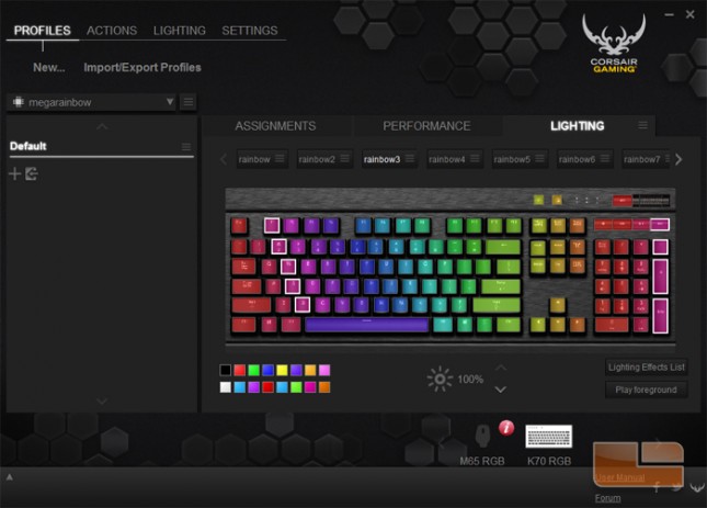
For my project, I have decided to create a series of RGB keyboard profiles that will change as the user interacts with it. Ideally, the final profile I create will feature designs that move on their own as well as specific user-initiated actions.

Through experimenting with the profiling software, I’ve found that animation is possible by setting the lights of each individual key to a series of keyframes, much like in more traditional animation. This means my next steps will be to:

  • Determine the kinds of animations that will be set to the keyboard, and how those animations will interact with the user
  • Map out animations on the keyboard in order to determine how to set the key layout
  • Create mockups of potential animations in order to determine the number of frames/framerate needed

Week of April 14th

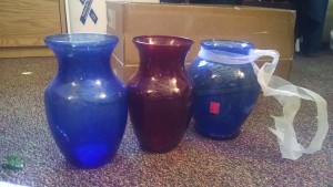
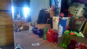
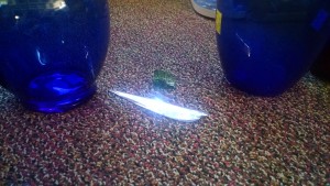
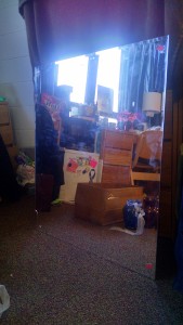
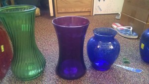
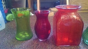
This week I have gone to goodwill and obtained my supplies for my project.

IMG_20160414_125828610 IMG_20160414_130023593 IMG_20160414_125958351_HDR IMG_20160414_125832516 IMG_20160414_130002042_HDR IMG_20160414_125821015 IMG_20160414_125816293

Today I plan to smash all the objects safely in a garbage bag.
The cost of all my objects came to:
Mirrors: 19.98

Vases: 27.34

Garbage bag: free

Hammer: free

Total: 47.32


After this I still have to obtain or buy rubber cement to put all the pieces together and possibly a light if a strong enough one is not available to me on campus already.

Construction_day2,3,4_~20hrs

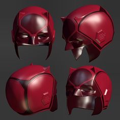
Hi again, So since the last post, I began working on the pants of the suit, and then moved on to building the sleeves and bracers of the main piece. I ordered and received: new brighter red thick vinyl fabric, and one helmet which will be converted into the flash cowl. I have also nearly completed the concept of the suit as well.

IMG_3718  Beneto_Flash_Regime2

Figure 2.1: helmet                       Figure 2.2: regime design

Y9uOpki

Figure 2.3: New helmet inspiration

when making the pants on day 2, I initially tried to make the suit’s pants covered entirely in leather, even sewing it down, but later had to cut out and replace this design with one which left the knees no longer covered. this was  a set back, and ended up nearly doubling my total time spent on day 2.

on day 3, I began working on the bracers, as seen bellow, and chose a new design for the suit overall. (as seen bellow). to make this design complete, I also ordered a helmet which will be made into the flash helmet seen bellow with just a few modifications.

the bracers were made using previously made bracers as a model, and utilized the recently acquired thick red fabric. However, the measurements were altered slightly to fit in some new improvements, as well as new aesthetic elements, such as the lightning on the back.

Figure 3.1: bracer construction

For day 4, Wednesday, April 13th, I began work on the sleeves, which were cut out of the jacket, and will eventually be sewn on to an under-piece for shoulder flexibility. the original jacket piece will be a separate vest, which will slide over, giving the appearance of it being one larger suit. I added the padding to one of the sleeves, and sewed it down, then cut the padding for the next sleeve, but ran out of time for that day. the final update on the peice as a whole is shown on figure 4.1

Figure 4.1: day 4 current progress

Proposal/Progress – Light Cube

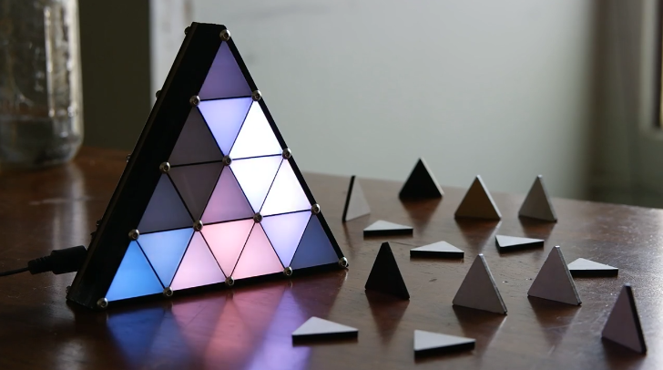
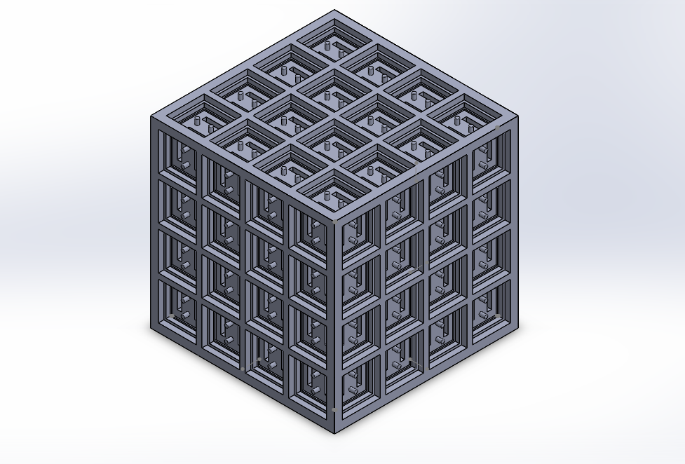
For my project I will create a cube, roughly 4×4 inches that has LED’s on each face. The LEDs will be controllable with scripts, allowing the project to be expandable. The patterns generated by the LEDs may be for visual stimuli or may convey information such as projecting a specific pattern based on the current weather.

This project is inspired by Micah Elizabeth Scott’s Triangle Attractor.
triangle attractor

Progress so far:
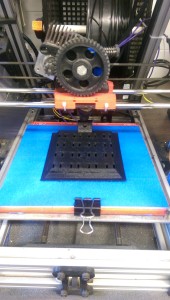
4x4 cubeI have modeled a rough draft of the structure for the cube.
IMAG0107

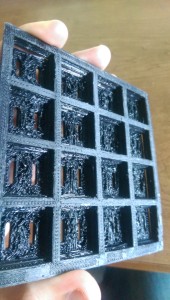
I have 3d printed one side of the cube.

IMAG0110

I ran into some challenges with the printing, as you can see in this picture, the inside of the individuals did not print correctly. I will have to make some changes to my design.

Next steps:

  • Wire LEDs into first side
  • cut acrylic squares to go on the cube faces
  • print more sides of cube
  • continue to assemble cube
  • begin writing scripts

Final Project Idea

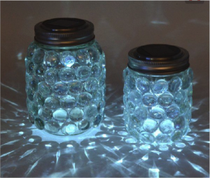
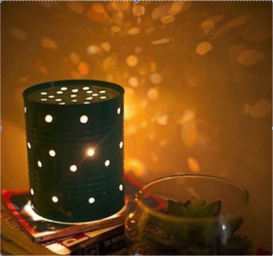
For my project, I have decided to combined my two favorite ideas together, which are the glass jar and tin can lanterns.  So I’m going to have two glass jars with marbles glued on the outside of the jar.  One jar will have only one type of marble color and the other jar will be multicolored marbles.  For the glass jar top, I’m going to pick a pattern and use different sized nails and a hammer to make the design on the top.   I have not decided on the design for the top yet but it is going to be a good one.  As for the lighting I’m going to be using LED battery operated lights.

Mason Jar LightCan lighting

Shopping List:

  • 2 glass jars
  • LED battery operated lights
  • Flat Marbles
  • Hot glue gun
  • Different sized nails
  • Hammer
  • Pattern design