Project Progress (week 2)

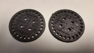
In the past week, I have fabricated and designed a few parts of the project. Above the 24 RGB LED ring will be 24 acrylic rods. Each rod will extend upwards from an LED. The rods will be held in place by 2 discs each with 24 rod holes and 24 pin holes.

I used Autodesk Inventor to design the discs and then 3D printed them. Below are images of the design on the computer and the discs during and after printing:
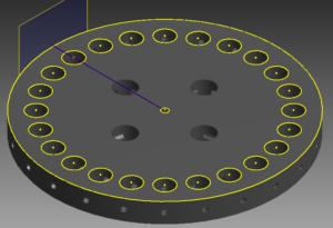
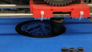
Disc_24_HolesDisc_printing Disc_printed Disc_printed Disc_printingIn addition to the discs, I started designing a way to produce interesting lighting effects on the LED ring. I thought of a mathematical software model where each LED is backed with a block that can send information to and receive information from the adjacent LED blocks. Each block will have an internal state that is converted to LED output and all 24 blocks will update periodically. I believe that because this a very general technique rather than a list of preprogrammed explicit patterns, it will produce interesting and unexpected lighting effects.

Project Progress

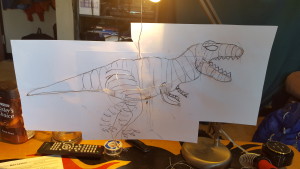
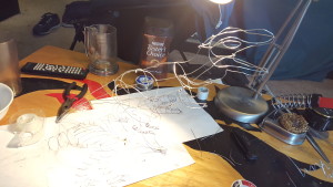
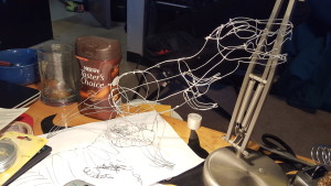
I now have the wire skeleton of T-rex built. I first increased the size of my sketch and started to make the silhouette by taping the wire down every few inches. Then I worked on 2D versions of the arms and legs. I started to build one half the dino on top of the paper and attached an arm and a leg. I then removed it from the paper and worked on the other side. I added supports to the arms and legs to give more shape and support. I finished it up by  adding features to the head like the eyes and teeth. I ordered the el wire, sound reactive inverter, and heat shrink tubing which I need to wait on to progress from here.20160407_00263220160410_15002020160410_16502120160411_12424220160414_180115


Project Progress

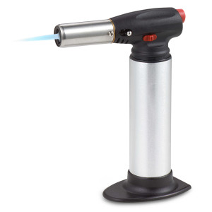
My new candy thermometer just came in yesterday. The LED lights should be coming in tomorrow so I can start to play around with the orientation of the lights and how to hook them up. So far I have been messing around with different ways to incorporate color into the sugar. Originally I thought that I could just heat up a knife under hot water to cut holes in the sugar globes. Unfortunately, that doesn’t make the knife hot enough. Although it takes more cleanup, I got my torch from back home so I’ve been torching knives to get them hot. This has been giving a very clean cut and has been more fun.

torch

Final Project Idea

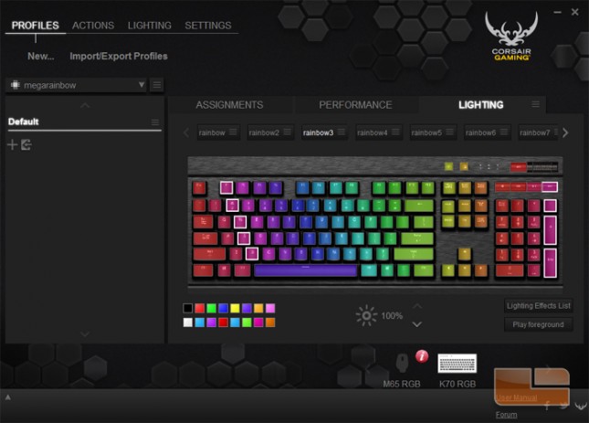
For my project, I have decided to create a series of RGB keyboard profiles that will change as the user interacts with it. Ideally, the final profile I create will feature designs that move on their own as well as specific user-initiated actions.

Through experimenting with the profiling software, I’ve found that animation is possible by setting the lights of each individual key to a series of keyframes, much like in more traditional animation. This means my next steps will be to:

  • Determine the kinds of animations that will be set to the keyboard, and how those animations will interact with the user
  • Map out animations on the keyboard in order to determine how to set the key layout
  • Create mockups of potential animations in order to determine the number of frames/framerate needed

Week of April 14th

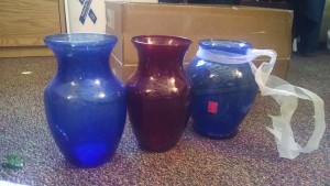
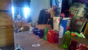
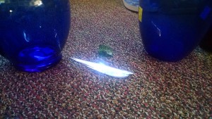
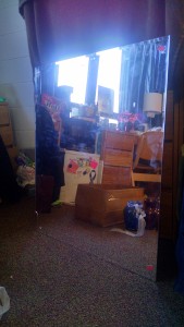
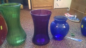
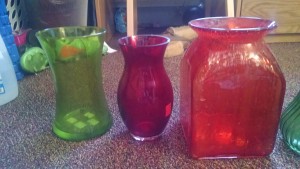
This week I have gone to goodwill and obtained my supplies for my project.

IMG_20160414_125828610 IMG_20160414_130023593 IMG_20160414_125958351_HDR IMG_20160414_125832516 IMG_20160414_130002042_HDR IMG_20160414_125821015 IMG_20160414_125816293

Today I plan to smash all the objects safely in a garbage bag.
The cost of all my objects came to:
Mirrors: 19.98

Vases: 27.34

Garbage bag: free

Hammer: free

Total: 47.32


After this I still have to obtain or buy rubber cement to put all the pieces together and possibly a light if a strong enough one is not available to me on campus already.

Construction_day2,3,4_~20hrs

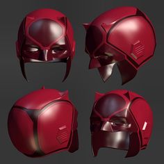
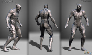
Hi again, So since the last post, I began working on the pants of the suit, and then moved on to building the sleeves and bracers of the main piece. I ordered and received: new brighter red thick vinyl fabric, and one helmet which will be converted into the flash cowl. I have also nearly completed the concept of the suit as well.

IMG_3718  Beneto_Flash_Regime2

Figure 2.1: helmet                       Figure 2.2: regime design

Y9uOpki

Figure 2.3: New helmet inspiration

when making the pants on day 2, I initially tried to make the suit’s pants covered entirely in leather, even sewing it down, but later had to cut out and replace this design with one which left the knees no longer covered. this was  a set back, and ended up nearly doubling my total time spent on day 2.

on day 3, I began working on the bracers, as seen bellow, and chose a new design for the suit overall. (as seen bellow). to make this design complete, I also ordered a helmet which will be made into the flash helmet seen bellow with just a few modifications.

the bracers were made using previously made bracers as a model, and utilized the recently acquired thick red fabric. However, the measurements were altered slightly to fit in some new improvements, as well as new aesthetic elements, such as the lightning on the back.

Figure 3.1: bracer construction

For day 4, Wednesday, April 13th, I began work on the sleeves, which were cut out of the jacket, and will eventually be sewn on to an under-piece for shoulder flexibility. the original jacket piece will be a separate vest, which will slide over, giving the appearance of it being one larger suit. I added the padding to one of the sleeves, and sewed it down, then cut the padding for the next sleeve, but ran out of time for that day. the final update on the peice as a whole is shown on figure 4.1

Figure 4.1: day 4 current progress

Proposal/Progress – Light Cube

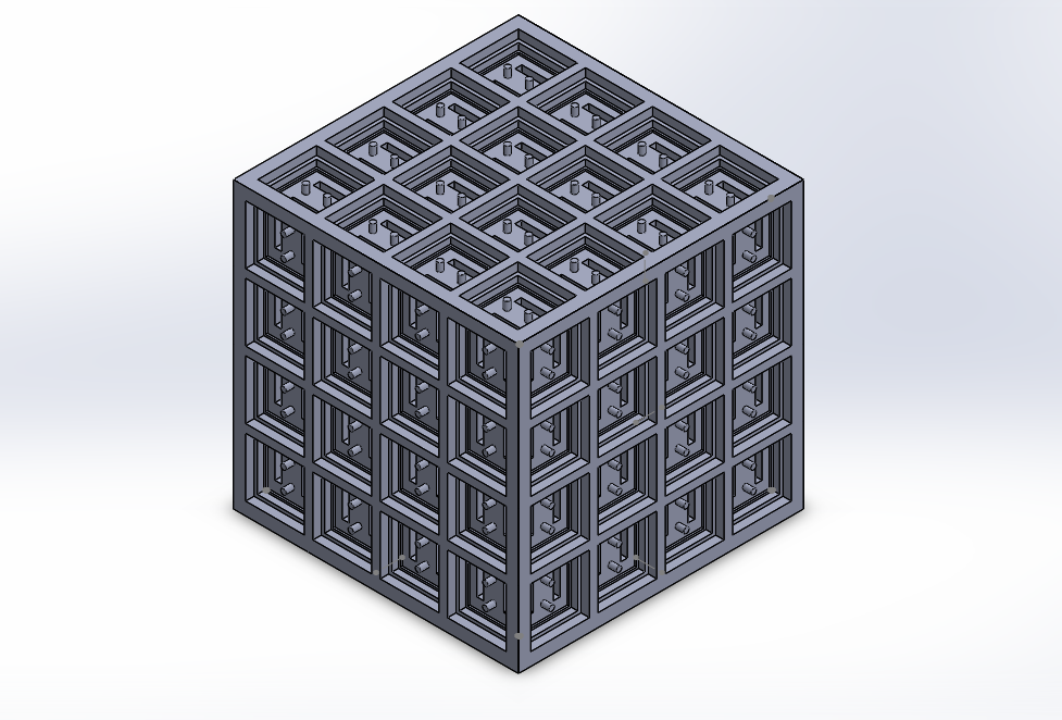
For my project I will create a cube, roughly 4×4 inches that has LED’s on each face. The LEDs will be controllable with scripts, allowing the project to be expandable. The patterns generated by the LEDs may be for visual stimuli or may convey information such as projecting a specific pattern based on the current weather.

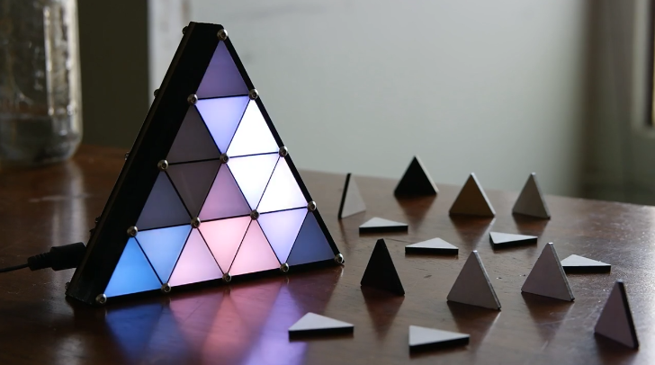
This project is inspired by Micah Elizabeth Scott’s Triangle Attractor.
triangle attractor

Progress so far:
4x4 cubeI have modeled a rough draft of the structure for the cube.
IMAG0107

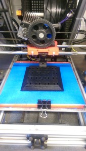
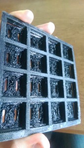
I have 3d printed one side of the cube.

IMAG0110

I ran into some challenges with the printing, as you can see in this picture, the inside of the individuals did not print correctly. I will have to make some changes to my design.

Next steps:

  • Wire LEDs into first side
  • cut acrylic squares to go on the cube faces
  • print more sides of cube
  • continue to assemble cube
  • begin writing scripts

Final Project Idea

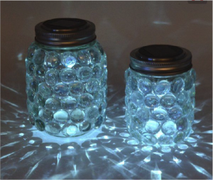
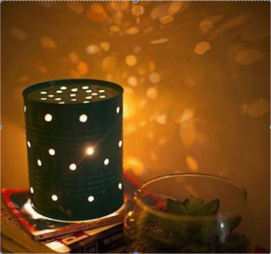
For my project, I have decided to combined my two favorite ideas together, which are the glass jar and tin can lanterns.  So I’m going to have two glass jars with marbles glued on the outside of the jar.  One jar will have only one type of marble color and the other jar will be multicolored marbles.  For the glass jar top, I’m going to pick a pattern and use different sized nails and a hammer to make the design on the top.   I have not decided on the design for the top yet but it is going to be a good one.  As for the lighting I’m going to be using LED battery operated lights.

Mason Jar LightCan lighting

Shopping List:

  • 2 glass jars
  • LED battery operated lights
  • Flat Marbles
  • Hot glue gun
  • Different sized nails
  • Hammer
  • Pattern design

Glowing Ferrofluid Patterns – Detailed Project Proposal

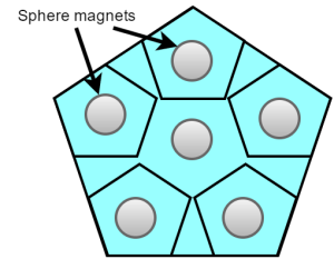
The block diagram of the chosen project, glowing ferrofluid patterns, is shown below. First of all, Processing will be used to extract the FFT data of a playing music track and transfer the FFT data to Arduino. On Arduino Uno, the FFT data will be quantized into six different frequency bins and the averaged amplitudes of the six frequency bins will drive the six vibration motors. The arrangement of the motors and magnets under the petri dish containing ferrofluid will be a pentagon-like shape since most petri dishes come in circular forms. After all that is done, the last task will be to 3D print a fixture to hold the petri dish so that the magnet and motor matrix can be inserted under the petri dish without touching it.

Untitled Diagram (5) Untitled Diagram (6)


Untitled Diagram (7)

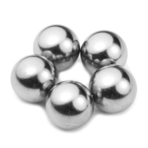
In the earlier version of the project proposal, it was proposed that nine motors will be used instead of six in order to add more freedom in the movement of the ferrofluid pattern; however, on second thought, the number of motors was reduced to six since an Arduino Uno that has six PWM output pins is already in possession. The physical shape of the magnets was chosen to be spherical so that the magnets can freely bounce and roll around within the confined pentagon shape when the motors underneath the magnets vibrate at different speed, resulting in more uniqueness in the change of magnetic field. Moreover, the vibration motors can draw up to 100mA at 5V full speed; therefore, it is required to have a separate power supply for the motors and this can be achieved by either using the power supplies in the ECE lab or purchasing a 5V battery for portability.

One challenge in the project is to design a medium between the magnet matrix and the motor matrix that will allow the sphere magnets to bounce around freely when the motors are vibrating. Since the motor discs are also made out of metallic element, the magnets will be sticking to the motors if a paper like medium is used. One way to resolve this challenge is to experiment the strength of the magnets as well as the attraction between the magnets and the motors and to even use a magnetic shield foil as the medium if necessary.

Picture1Picture2

Up to this point, all the necessary items in the following list have been purchased and I am working on extracting the real-time FFT data of a playing music track using Processing. The next step will be to get the communication between Processing and Arduino up and running with the FFT data.

Shopping List

  • Ferrofluid – 2oz
  • 6 Sphere magnets
  • 10 Glow sticks
  • 6 Mini vibration disc motors
  • Petri dishes


Project Progress (week 1)

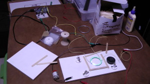
In the past week, I bought the most important part that I will use in my project. This is the RGB LED light ring. I soldered wires to the ring and tested it. Below are two images of the setup. I connected the ring to a 5 volt power supply in the top right of the upper photograph. I also connected the ring to the Arduino in top left of the upper photograph.

LED_Ring_Test_1

LED_Ring_Test_2

For my project, I would like to have a rotating piece in the middle of the ring with parts on it that interact with the light. After thinking about many possibilities, I have decided to use 24 acrylic rods. Each rod will be mounted to a piece in the middle of the ring that will hold it directly above an LED on the ring. The 24 rods will be able to rotate around the ring.

These are the items that I need to buy before I can move forward with the project:

  • 24 3/16″ Acrylic Rods
  • 2 Gears: 1 large and 1 small (will connect a motor to the rotating center piece)
  • 1 Metal Rod (will hold the rotating center piece in position and allow it to rotate)
  • Wire in multiple colors